](/media/headers/pcb.jpg) Image credit: pixabay
Image credit: pixabay
PCB0003 - Breadboard supply
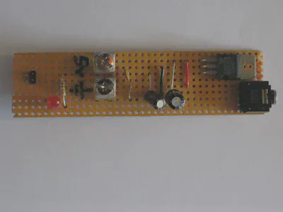
This is a very simple PCB based on the LM317 voltage regulator. For years I used a 7805 on the stripboard below, a fixed 5v output and really poor layout on my behalf.

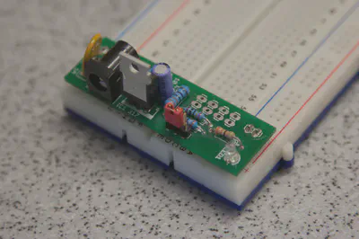
The PCB sits across the end of a normal breadboard and powers both rails. The input is protected with a resettable PTC fuse and the output is selectable between 3.3v and 5v using a jumper.

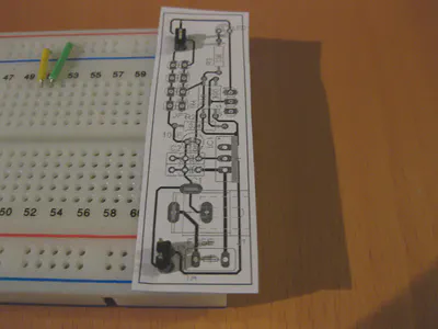
Spacing of the 2 pin headers for the breadboard rails was achieved using the highly technical method of “try it and see”. It transpires that the theoretical measurements are quite precise. Printing a circuit onto paper like this is an excellent way of making sure your parts fit before sending it off for manufacture.

Revision2 boards have a diode in series with the input (to protect against reverse connection of the power supply), better spacing for the optional output headers and holes for an alternate input (e.g. a 9V battery).
Download
- Download board (ZIP) - Eagle files
- Download schematic (PDF) - Original design
License
This work is made available under the Creative Commons Attribution-NonCommercial-ShareAlike (CC BY-NC-SA) license.