Using the hardware USART with BoostC and a PIC
This post looks at what is needed to get a serial connectiong working with BoostC using a PIC with a hardware USART. A later post will cover the BoostC software implementation, when I have finished figuring it out.
By the end of this post there will be a PIC uC talking to Hyperterminal on the PC using less than 50 lines of code.
Pros & cons of using the BoostC library
There main advantage to using this library to implement serial communication is that it sets up all registers and control bits for you (including TRIS for the TX and RX pins). This means limited digging around in the datasheet, you can code without worrying about the underlying hardware.
However it may be a disadvantage too. The limited control over the hardware means that certain things are fixed. For example, 8-bit transmission is the default. It might be possible to change these by modifying the PIC registers directly but I haven’t tried this yet. Leave a comment if you know it works!
Requirements
A few things are necessary to make this work. Firstly a PIC with hardware USART support, in this post I’ll be using the PIC 18F1320 as an example. The hardware USART is listed under “peripherals” in datasheets.
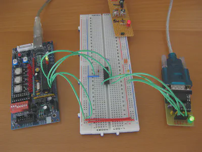
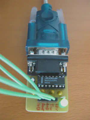
In order to talk to a PC we also need some form of level convertor from logic levels (+5v/0v) to RS-232 (maximum voltage range +12/-12v). I use a MAX232 breakout board that I built myself, but this board or this board from Sparkfun should work just fine.
Connecting it up
The purpose of this post isn’t to discuss connectivity, but briefly the PIC TX and RX pins need to be connected to the level shifter, as do +5v and GND. The serial pins on the PIC can be found in diagrams in the datasheet. Remember which pins they are as they are needed later.
Find the right values
The BoostC library is incredibly easy to use but there are a three values to work out first. Remember the choices so they can be used in the code later.
Bit time
The first value is bit_time, which is the number of CPU instruction cycles per bit (note that the header file says this is used by the software USART, but code will not compile without it so it is included here for reference).
Take the clock speed in hz, divide by four and then divide by your desired bit rate. I recommend starting slow (e.g. 1200 baud) and trying to faster when it works, so for an 8Mhz clock and 1200 baud we get:
$$ \text{bit_time} = \frac{8000000}{\frac{4}{1200}} = 1666 $$
Baud rate generator mode
The second thing to work out is whether we need high or low speed mode and what divisor to use. Fortunately these are fairly simple as they are explained in the datasheet.
If using a slow baud rate with a fast oscillator, the datasheet recommends using the high baud rate generator. The datasheet also suggests that it might help to reduce baud rate error. Enabling this means using a mode of 1.
For this example I used the 8Mhz internal oscillator (fairly low speed) and did not use the high speed generator, so I set mode to 0.
Baud rate generator divisor
Finding the divisor number is as easy as reading the datasheet to find the “SPBRG value”. There are tables with the combinations of oscillator speed and baud rate showing the correct value. Be careful to use the correct table for whether you plan to work with the high or low speed generator!
For 1200 baud at 8Mhz using the low speed generator, the value is 103.
Using the code
Below is example code which shows how to use the information described above. It was adapted from the file serial_test.c which comes with BoostC.
For some reason the BoostC examples use the hexadecimal locations of the correct registers. It is possible to use their names instead, e.g. TRISB/LATB/PORTB as I have below.
In the code below it is necessary to change 4 things:
- the ports and pin numbers for
TXandRX(e.g. ifTXisRA6, use 6) - the
bit_timevalue calculated above - the call to
uart_init, which will need the high/low speed flag and the divisor value - the clock frequency, if 8Mhz is not used
Code example
/********
*   Date: 11th April 2010
* Author: David Cannings
*
* Example BoostC code for hardware USART on a PIC18F1320
********/
#pragma CLOCK_FREQ 8000000

#include <system.h>

// Standard 18F1320 configuration, included to pacify PICkit2
#pragma DATA  _CONFIG1H, _IESO_ON_1H & _INTIO2_OSC_1H
#pragma DATA  _CONFIG2L, _PWRT_ON_2L & _BOR_OFF_2L
#pragma DATA  _CONFIG2H, _WDT_OFF_2H
#pragma DATA  _CONFIG3H, _MCLRE_ON_3H
#pragma DATA  _CONFIG4L, _DEBUG_OFF_4L
#pragma DATA  _CONFIG5L, _CP0_OFF_5L & _CP1_OFF_5L
#pragma DATA  _CONFIG5H, _CPB_OFF_5H & _CPD_OFF_5H
#pragma DATA  _CONFIG6L, _WRT0_OFF_6L & _WRT1_OFF_6L
#pragma DATA  _CONFIG6H, _WRTC_OFF_6H & _WRTB_OFF_6H & _WRTD_OFF_6H
#pragma DATA  _CONFIG7L, _EBTR0_OFF_7L & _EBTR1_OFF_7L
#pragma DATA  _CONFIG7H, _EBTRB_OFF_7H

// Setup the hardware USART
// TODO: Set the next 6 values to the right ports and pin numbers
#define TX_PORT     PORTB
#define TX_TRIS     TRISB
#define TX_BIT      1
#define RX_PORT     PORTB
#define RX_TRIS     TRISB
#define RX_BIT      4

// The following values are for 18F parts, for 16F see rs232_driver.h
#define e_SPBRG     0x0faf
#define e_RCREG     0x0fae
#define e_TXREG     0x0fad
#define e_TXSTA     0x0fac
#define e_RCSTA     0x0fab
#define e_TXIF_PIR  0x0f9e
#define e_RCIF_PIR  0x0f9e
#define e_TXIF_BIT  4
#define e_RCIF_BIT  5
#define MODE        (USART_reset_wdt | USART_HW)

// bit_time = FOSC / 4 / baud_rate, so 1200 baud at 8Mhz
// TODO: Set bit_time here
#define bit_time 1666

#include <rs232_driver.h>

void main() {
    osccon = 0x72;  // 8Mhz internal oscillator

    adcon0 = 0x00;  // Disable internal ADC
    adcon1 = 0x7F;  // Set all PORTB to digital I/O

    // Setup the USART, arguments are baud rate generator mode
    // and divisor
    // TODO: Set mode and divisor here
    // I chose 0 for low speed mode and 103 for 1200 baud at 8Mhz
    uart_init(0,103);

    // Send some text from the PIC to PC
    puts("Hello, world");

    while (1)
    {
        // If a character is received from the PC, send it back
        if (kbhit())
        {
            puts("You pressed: ");
            putc(getc());
            puts("");
        }
    }
}
Setting up a PC client
As I mentioned above the settings for serial communication are fixed by the library. You will need to set 1200 bits per second, 8 data bits, no parity, 1 stop bit and Xon/Xoff flow control. This is often shortened to “1200 8-N-1”.
If you use Hyperterminal, all settings are on the properties page for the relevant serial port.
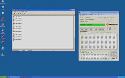
Conclusion
And finally, some proof that it actually works! If you find this post useful, or you need further help, please leave a comment below.
Update
Mike (K8LH) has posted a great little utility on the Microchip forums that can help work out the correct values, if you don’t fancy digging through datasheets.
David Cannings
Cyber Security
My interests include computer security, digital electronics and writing tools to help analysis of cyber attacks.