Cooking with gas, my first SMD board
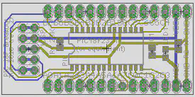
My first bunch of boards arrived back from BatchPCB and I’m really impressed. Great printing for the silkscreen and a really professional looking product. One of the boards I ordered was a breakout board for the SMD PIC 18F2321, the first surface mount board I have tried.
The original board was designed and kindly sent to me by 3v0, I tidied up the silkscreen before shipping it off to be produced.
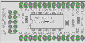
This board uses 0803 SMD parts, but boy are they tiny. These are some of the larger surface mount components, I definitely would not try the smaller ones. After applying paste by hand to the board (I used this stuff) I carefully placed the components using a pair of tweezers I bought specially.
Most board houses will apply a solder mask to manufactured PCBs, this is a special layer on top of the board that covers up everything except the pads. This means a thin line of paste can be run along all the pins of the chip, there is no need to try and put an individual dot on every pad! As the paste heats up and turns into solder the flux will evaporate and surface tension pulls the solder paste back onto each pad.
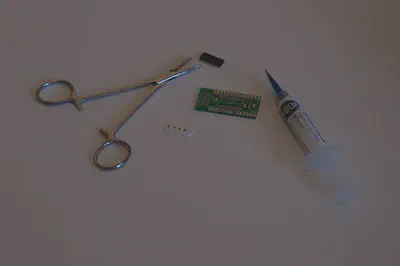
The original board, paste and tweezers can be seen in the image below.
After assembly came the fun bit, cooking time! I kept an old frying pan specially for this, into which I placed the board. Cooking time was no more than a few minutes, it is very visible when the paste starts to reflow and turn into molten solder. As soon as that happened I turned off the gas hob and left it to cool.
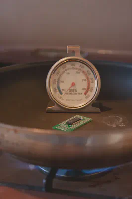
Note that the oven thermometer really doesn’t work, it had barely reached 50°C by the time the board was finished. A non contact IR thermometer apparently works much better and should be considered if you want to roughly follow a specific reflow profile.
The final result is shown below, after the header pins were hand soldered.
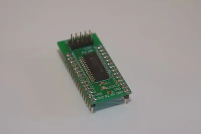
Did it work first time? Well, mostly. The PIC powered up, the LED blinked on and it talked to PICKit2 on the PC. After a little examination I found that two of the pads on the chip were not properly soldered, which played havoc with some code I was writing.
Next time I think I would use more paste, I was quite frugal with the syringe and had to fix the two bad joints by hand. I also probably wouldn’t design all future PCBs as SMD, populating and reflowing the board is easy but the parts are fairly expensive compared to standard “through hole” alternatives.
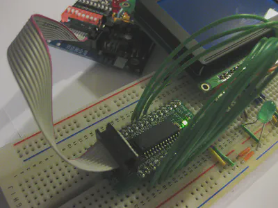
One more picture now of it in use. This little thing really speeds up prototyping time, no need to connect a pull-up resistor, power and ICSP lines manually. If only writing code was so easy..
For more information, watch this useful video on Youtube and read the excellent SMD How To from Sparkfun.
David Cannings
Cyber Security
My interests include computer security, digital electronics and writing tools to help analysis of cyber attacks.