Measuring PIC Vdd with no external components using the FVR
Microchip’s Application Note AN1333 hints at a useful technique for measuring the Vdd of a PIC using only the internal Fixed Voltage Reference (FVR) module.
This page explores how to use this for a rough measurement of the current Vdd, saving pins and reducing complexity.
The application note says that:
For unregulated applications, the supply voltage can be determined from a conversion of the internal fixed voltage reference
During operation, the supply voltage can be determined by performing an analog to digital conversion of the fixed voltage reference
After reading the two quotes above I spent an evening working out the technique on a PIC 18F25K22. I then read the original paper more thoroughly and found the link to Application Note AN1072 which explains how it works on PICs with a 0.6V or 1.2V reference. These are less common now and have been replaced with the FVR module which supports 1.024V, 2.048V or 4.096V outputs.
Why is this useful?
It is often useful to know the supply voltage of a microcontroller for applications such as determining battery voltage or using the in-built temperature indication circuit.
Typical approaches for measuring Vdd use an external resistor divider and a single analogue input. This takes up a valuable port pin (especially on 8 pin devices) and still requires use of the FVR module or an external reference to ensure it yields accurate results. Some (small) amount of current also flows through this divider at all times which might be a problem for long life battery powered devices. In addition you can save on PCB space and routing for the two tiny SMD resistors!
Using the FVR module, which can be disabled when not in use, offers a low power alternative with no external components.
What PICs does it work on
The Microchip parametric search shows over 40 PICs that include a bandgap reference. Among these are the 12F1822 and 12F1840, 18F parts with K or J in the name and some 16F parts.
Crucially it requires a microcontroller with a fixed voltage reference. References which depend on Vdd - called ratiometric references - are not suitable as there is no known voltage anywhere in the system.
How it works
In order to calculate our unknown Vdd we need a known value to compare it against, which the Fixed Voltage Reference (FVR) module provides. Normally the FVR would supply a stable reference voltage for the ADC, but close inspection of the datasheet shows that it can also be used as an input.
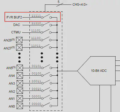
If the FVR buffer is selected by setting CHS to 0b11111 and Vdd is the positive reference, the ADC module will return a measurement of the fixed 1.024v. This will vary depending on the value of Vdd and allows calculation of the top end of the ADC scale, which will correspond with Vdd:
$$ V_{\text{DD}} = \frac{2^{10}}{\text{Val}_{\text{ADC}}} \times V_{\text{FVR}} $$
Therefore:
$$ V_{\text{DD}} = \frac{1024}{\text{Val}_{\text{ADC}}} \times 1.024 $$
Note that whilst other registers may change, the ADC input setting of 0b11111 is the same for all devices.
PIC register setup
The code below uses Microchip’s XC8 register names and is designed for a PIC 18F25K22. A few changes may be required for other parts.
VREFCON0bits.FVRS = 0b01;   // Internal 1.024v ref
FVREN = 1;                  // Enable FVR module
while(!FVRST);              // Wait for FVR to be stable

ADCON2bits.ADFM = 1;        // Right justify result
ADCON0bits.CHS = 0b11111;   // FVR is ADC input
ADCON1bits.PVCFG = 0b00;    // Positive ref is Vdd (default)
ADCON1bits.NVCFG = 0b00;    // Negative ref is GND (default)
ADCON0bits.ADON = 1;        // Turn on ADC module
Taking a measurement
Measuring the FVR is no different to any other usage of the ADC module, but the code below is included for completeness.
int adc_val = 0;

ADCON0bits.GO = 1;          // Start a conversion
while (!ADCON0bits.DONE);   // Wait for it to be completed

adc_val = (ADRESH << 8);    // Store the result in adc_val
adc_val |= ADRESL;
Calculating Vdd (floating point)
Using floating point math provides the most accurate results but requires a lot of code space for the required libraries. The equation above can be implemented in XC8 like so:
float vdd = (1024.0 / adc_val) * 1.024;This returns a value in volts, but might use a large portion of your ROM space!
Calculating Vdd (integer maths)
For smaller code size it is necessary to stick to integer maths. The simplest method for this provides reasonable results with a minimum of instructions.
int millivolts = (8192 / adc_val) * 1024;
millivolts /= 8;
Accuracy and error
Using floating point the error can be kept below 0.5%. With integer math only and no calibration error is worse, but under 3% over a Vdd of 3V. An Excel spreadsheet (download link below) allows calculation of percentage error for differing input values.
Note that these values assume that the FVR is a perfect reference, which is not the case. For 18F parts check parameter VR01 in the analog characteristics section. This instability of the FVR over temperature and voltage can introduce additional error which should be considered depending on your application.
| Vdd | ADC | Floating point (volts) | Integer (millivolts) |
|---|---|---|---|
| 1.25 | 838 | 1.25 (0.10%) | 1152 (7.84%) |
| 1.5 | 699 | 1.5 (0.01%) | 1408 (6.13%) |
| 1.75 | 599 | 1.75 (0.03%) | 1664 (4.91%) |
| 2 | 524 | 2.00 (0.05%) | 1920 (4.00%) |
| 2.25 | 466 | 2.25 (0.01%) | 2176 (3.29%) |
| 2.5 | 419 | 2.50 (0.10%) | 2432 (2.72%) |
| 2.75 | 381 | 2.75 (0.08%) | 2688 (2.25%) |
| 3 | 349 | 3.00 (0.15%) | 2944 (1.87%) |
| 3.25 | 322 | 3.25 (0.20%) | 3200 (1.54%) |
| 3.5 | 299 | 3.50 (0.20%) | 3456 (1.26%) |
| 3.75 | 279 | 3.75 (0.22%) | 3712 (1.01%) |
| 4 | 262 | 4.00 (0.05%) | 3968 (0.80%) |
| 4.25 | 246 | 4.26 (0.29%) | 4224 (0.61%) |
| 4.5 | 233 | 4.5 (0.01%) | 4480 (0.44%) |
| 4.75 | 220 | 4.77 (0.34%) | 4736 (0.29%) |
| 5 | 209 | 5.017 (0.34%) | 4992 (0.16%) |
| 5.25 | 199 | 5.27 (0.37%) | 5248 (0.04%) |
| 5.5 | 190 | 5.52 (0.34%) | 5504 (0.07%) |
If you absolutely need small code and good results then read the Microchip application note above and inspect the mechanism used to store a calibrated reading. This allows the use of integer maths with reasonable accuracy.
Example
Download a sample project
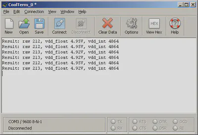
The sample project below can be used with an 18F25K22. Connect the chip as usual (power, MCLR, decoupling capacitors etc) and the Vdd voltage will be written to the UART on pin RC6 (TX1).
- Download project (ZIP) - MPLABX project for use with an 18F25K22 and the Microchip XC8 compiler. Also includes an example
.hexfile for burning straight to a 18F25K22. - [Download Excel Spreadsheet (XLSX)](/downloads/electronics/ADC error values for FVR Vdd calculation.xlsx) - A simple spreadsheet for calculating error.
Addendum
There were some useful comments on the original version of this page. Rather than edit the changes into the page I have included the comments verbatim below.
Philippe
Hi, Your integer result is not accurate due to your methodology.
Long math is common and quite compact with much compilers.
You may achieve quite the same theoretical 0.1% accuracy than with floats by using long integer math:
int millivolts = 1048576L / adc_val;
Another usage of FVR: If all you need is to check a Vdd value (eg to detect a “low bat” state, another way to use FVR is to compute at compile time an int threshold in ADC points and simply compare the ADC value to it: no runtime computations. I used this method some time ago: http://www.pmpcomp.fr/articles.php?lng=en&pg=439
Best regards, Philippe.
Matt Bennett
Unfortunately, there is a very good reason why you don’t see this very often- the FVR isn’t very ‘F’ - it can vary by as much as 5% on the PIC18 you mention, and by -8 to +6% on the 12LF1840- and these aren’t errata - these are the published and tested specs- they aren’t very good references- you would need to take into account the amount the reference can vary over temperature and voltage. I don’t believe that the chart you posted takes the variance into account
It is great to get a rough estimate, … you may be able to calibrate each part- if you want any kind of precision, you’ll need to use an external FVR.
Matt Bennett
Just outside of Austin, TX
30.51,-97.91
The views I express are my own, not that of my employer, a large multinational corporation that you are familiar with.
Piotr
In 16-bit integer math I would do it like this:
unsigned int millivolts = (65535 / adc_val) « 4;
It’s both faster and more accurate than your equation. I did the same calculations you did but with 10mV step. Highest error in your equation is 9.29%, in my equation the highest error is just 1.07%. Actually you gave me the idea, I just put it to extreme - if higher numerator helps, then why don’t use the highest numerator possible in 16-bit variable?
Of course you still need to consider ADC errors (offset, gain, integral, differential) and inaccuaracy of FVR. In my project total error of this measurement is slightly below 6% which is acceptable.