The ST7565 display controller
This page covers the theory of using a graphic LCD based on the ST7565 controller. These are widely available with popular sizes of 132x32 and 128x64, a number cost below £10.
The tutorial follows the same path I took whilst developing a simple library for a screen I had bought. I set myself the challenge of doing this from scratch, rather than using code from the internet.
Whilst this post uses a 128x64 screen as an example it is equally applicable to different sizes.
Pros
- Easy to interface using fewer pins than other graphic LCDs
- Onboard voltage booster for the liquid crystal display
- Software controlled contrast and rotation
- Works at faster clock speeds
- Good selection of backlight colours
Cons
- 3.3v logic only (not such a problem any more)
- In SPI mode a large buffer is required in local memory
Getting started
The most important thing needed when developing a library is a good datasheet. The information provided by screen manufacturers is often lacking in detail or quality. The datasheet I used can be found here.
Basic operation (hardware)
The most basic pinout for the ST7565 is shown below. To drive it from a microcontroller in SPI mode 5 pins are required. All of these pins are outputs from the microcontroller and inputs to the screen. Because it is not possible to read from the screen there is no requirement for inputs.
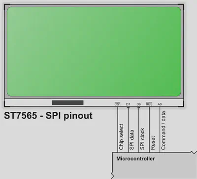
It is necessary to connect RESET to the microcontroller as the initialisation procedure involves toggling this pin. This pin should not be tied high or low or it may not be possible to reset the screen correctly.
Depending on your GLCD module it may be necessary to connect a number of capacitors, this is discussed in the next section.
Voltage boosting and regulation
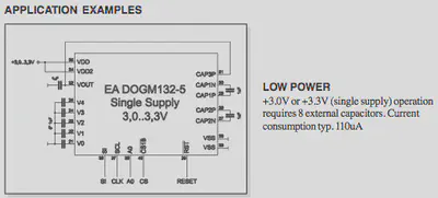
The ST7565 has an integrated voltage booster (charge pump) circuit that can provide the high voltages needed by the liquid crystal display. If the circuit only has a single supply such as 3.3v then the charge pump is the easiest way to power the screen. If the circuit contains a voltage source of between 9v and 12v then it is possible to reduce the number of external components needed by using this directly.
The internal booster can provide from 2x to 6x the input voltage depending on how capacitors are connected between the CAPxx terminals. Full details are provided on page 31 to 34 of the datasheet above. The only limitation is that the maximum voltage after boosting must not exceed Vout, which is 13.5v.
Many LCD specific datasheets will provide the exact capacitors required for a particular model. For some display modules these capacitors are included on the circuit board and do not need to be added. Check the datasheet carefully! For example, the image below is taken from the datasheet for an inexpensive model available from Mouser, the EA DOGM132-5:
In addition to the voltage booster the ST7565 contains an integrated voltage regulator. This has 8 steps and regulates the reference voltage used to drive the liquid crystal display. It is necessary to find a value between 0 and 7 which works well with the specific hardware as this is used with the dynamic contrast feature. Typically a “middle” value such as 3 will work with any screen.
Basic operation (software)
SPI mode provides an easy mechanism to drive the screen using few pins. A single bit is written to the data pin and the clock is pulsed high then low. The implementation of SPI by the ST7565 is fairly standard, more information can be found on the Wikipedia SPI Bus page.
One limitation of using the screen in SPI mode is that it only supports writing commands or data. It is not possible to read from the screen therefore it is necessary to keep a copy of the current screen data in memory on the microcontroller. The size of this software buffer can be calculated easily, there are 128 columns and 64 rows for a total of 8192 bits (1 bit per pixel for black and white). Therefore 1024 bytes in total are required to store a copy of the screen, which can be a large amount on many smaller microcontrollers.
With software (‘bit banged’) SPI it is possible to use the screen at very fast clock speeds. On an PIC 18F I have used my screen with a 64Mhz internal oscillator and it works absolutely fine. It is possible to calculate (or simulate/measure) whether the microcontroller can exceed the ST7565 minimum clock period.
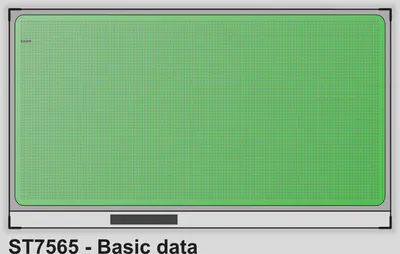
Screen layout
Unlike displays using the KS0108 the ST7565 has a single controller for the whole screen. There is no need to swap between the left and right in order to send commands.
A 128x64 screen is made up of 8 pages, each of which is 8 pixels high and 132 wide. This maps nicely to the software buffer required for caching the screen contents because each page is a byte high.
![]()
It is easiest to imagine the top left of the screen as 0,0 and the bottom right as 127,63. This makes some of the maths required in software much easier. To write data at (0,0) it is necessary to select page 0, column 0 and then set the individual bit. In contrast the location (32,32) is in page 5. The simplest method of writing data to the screen is to send a whole page at a time, starting from the left in column 0 and continuining to the right at column 127.
Sending a command to the screen
Issuing a single command to the screen is the most basic building block of the interface code. The steps required are:
- Set the A0 pin low to indicate that command data is being sent
- Set the chip select (CS) pin low
- Send each bit of the command, starting with the most significant bit and working down to the least significant
- Set the chip select (CS) pin high, to free the bus
Therefore the “display on” command (which is 0xAF or 0b10101111) should be sent as: 1, 0, 1, 0, 1, 1, 1, 1.
As long as the SPI timings are not violated there is no need to introduce any delays as the screen will never be “busy”.
Screen initialisation
Now that we can send a single command to we need to follow a number of steps to setup the screen.
- Strobe the RESET pin low then high, to initiate a hardware reset
- Setup the duty cycle (either 1/7 or 1/9) depending on the physical LCD
- Set the horizontal and vertical orientation to a known state
- Configure the internal resistor divider which is used by the voltage regulator
- Turn on the internal voltage booster to provide power to the LCD glass
- Initialise the dynamic contrast to a default value
- Reset the current display position to the top left
The commands for these are a single byte except the dynamic contrast, which is explained later. Below is an image captured from a logic analyser while the initialisation code runs.
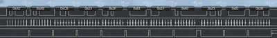
In this trace the following things can be seen:
- Command
0xA2: set the LCD bias to 1/9th - Command
0xA0: horizontally “normal” (not flipped) - Command
0xC8: vertically “flipped” (complements the command above) - Command
0x23: the internal resistor divider set to 3 (from 0..7) - Command
0x2F: power control, all internal blocks ON - Command
0x81: enter dynamic contrast mode - Data for the dynamic contrast mode, set to 31 (from 0..63)
- Command
0x40: go back to the top left of the display
When power is first applied to the screen it is also important to clear the onboard screen memory. As it is non-volatile RAM it will start in an unknown state.
Sending data to the screen
The only difference between sending a command and data is the A0 pin. When sending data the A0 pin must be high to differentiate the bus data from a command.
To start we send a command to reset the position to the top left corner (0,0). After this a quick trick is to write a single byte and see how it is displayed. It is important to know which way round the screen will display the data it receives, whether the “most significant bit” or “least significant bit” is displayed at the top. The illustration below shows the output if the byte 0x80 is sent four times to the screen:
From this it can be seen that the most significant bit displays at the bottom of the page. The first bit we send is at the bottom, then subsequent bits work upwards toward the top of the page. This will be important later when we try to set an individual pixel.
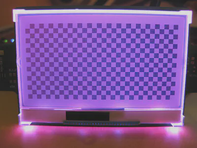
Displaying a basic test pattern
The easiest way to test if the driver code is working is to send a very basic test pattern. A quick check is to send constant bytes of 0xFF to fill the screen. If this works then variations can be tried, such as 0xF0 or 0xAA.
At the end of each row, after every 128 bytes, it is necessary to select the next page and move to the start of the row. The following image is the basic test card I used to demonstrate that my display was wired up correctly.
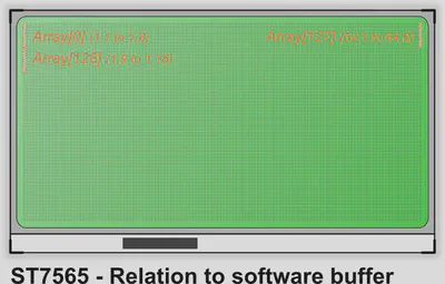
Writing to specific pixels
Writing specific pixels opens up a whole world of possibilities from lines, circles, 1 bit-per-pixel graphics and variable height fonts. As these graphics functions are not dependant on a specific controller or screen it is best to split them out into a separate library which is portable across any screen. This is perhaps the most difficult portion whilst developing a library to work with any screen.
In order to set a specific pixel it is necessary to break the process into a number of steps:
- Find the corresponding byte in the software buffer
- Calculate the bit within this byte
- Use logical XOR (to set the bit) or AND (to clear the bit)
Finding the correct byte is straightforward. The first position in our array is at the top left of the screen. The 128th byte in the array (Array[127]) is on the first page at the right hand side of the screen. The next bit “wraps” to the next page, at page 1 column 1.
To calculate which byte we need to use we need to divide the Y position by 8 and multiple the result by 128. To this we add the X position, then subtract 1 (as C arrays start from 0). The equation $ X + ({ \frac{Y}{8} \times 128 }) - 1 $ works well in C. To verify this is correct:
- (1,1) on the screen would give $ 1 + ( \frac{1}{8} \times 128 ) - 1 = 0 $
- (61,52) on the screen would give $ 61 + ( \frac{52}{8} \times 128 ) - 1 = 828 $
To calculate the bit inside this byte we must remember that the 8th (most significant) bit appears at the bottom of the page. So to write to Y location 8 we need to set the 8th bit of a byte on the first page. To write to Y location 16 we need to write to the 8th bit of the corresponding byte on the second page. Therefore we need the remainder after the Y position is divided by 8, which can be found using the modulo operator. This is as simple as Y % 8:
- (1,1) means setting 1 % 8 = the 1st bit
- (61,49) means setting 49 % 8 = the 1st bit
- (61,53) means setting 53 % 8 = the 5th bit
It is now possible to set the correct bit inside the byte, on PIC microcontrollers this can be achieved using very efficient bit operators such as bsf or bcf.
Displaying text
Like many other graphic LCDs the ST7565 has no built-in font. The quickest & easiest way of displaying text on this screen is to define an 8 pixel high font. This maps directly to one page (or ’line’) of the display and therefore we can use very fast instructions to copy the data from a predefined font to the right area of the screen.
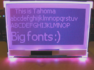
However this limits us to a fixed height and only 8 lines of the screen. Now that we know how to set individual pixels there are much nicer ways of displaying text. Consider the following image:
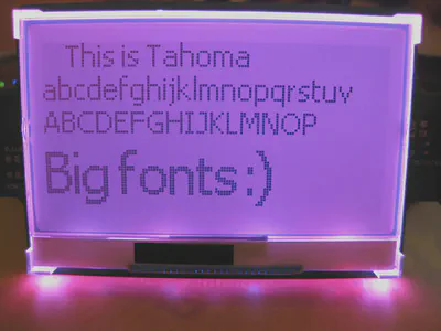
Larger fonts take up more room but can be used to provide a much nicer looking user interface for a project. With the knowledge that we can set a specific pixel it is easy to make advanced graphics functions. However these are separate to the ST7565 screen itself, so I will cover them in a future blog post. Impatient readers can check my graphics library (Doxygen documentation can be found here).
Using advanced features
So far all of the features are common to all standard graphic LCDs. However there are a number of additional tricks that ST7565 based displays can offer.
Inverting the screen
With a single command the ST7565 can be instructed to invert the display. This can be useful for emphasis or to make the screen easier to read in certain situations. The command “display normal or reverse” is 0b1010011X, where X is 1 for reversed or 0 for normal.
The picture below shows the same font demonstration as above, but with the inverse feature turned on.
Blacking the screen
The ST7565 is capable of setting all points on the display to black without affecting the screen RAM. Whilst it is hard to think of a situation where this might be useful the command “display all points” is a single byte and can be used to turn the display black if required.
Dynamic contrast control
Unlike other common graphic LCDs the contrast for the ST7565 is set by an internal resistor divider. This means that it can be set in software and altered dynamically. To change the contrast we need to send two commands. The first enters “volume mode set” and the second sets the contrast from 0..63.
The number of useful steps may be less than 64, on my test screen the visible steps are from 12 (very light) to 40 (very dark). Lower values are not visible as the voltage is too low, higher values make the screen completely black as there is no distinction between pixels which are off or on.
This feature could be used with a light sensor to dim the screen depending on ambient conditions. It can also be used to fade the screen in or out.
Screen rotation and mirroring
In the same way that the screen can be inverted without affecting the display data it is possible to flip the screen in either the horizontal or vertical direction. This means that the screen can be used either way up with no changes required to the software except sending extra two commands to the screen.
Flipping the screen horizontally (from left to right) is achieved with the confusingly named “ADC Select” command. Flipping the screen vertically (from top to bottom) is possible with the “COM Output Mode Select” command. Unless you want to view the screen in a mirror it is necessary to use both commands at once!
As mentioned earlier the memory on the screen is actually 132 columns wide, to support a maximum screen size of 132x64. On 128 pixel wide models there is an important consideration if rotating the display. If the screen is not rotated as the extra 4 rows are on the right hand side and not visible, as illustrated below:
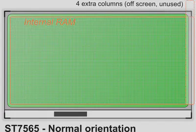
When the screen is rotated the controller outputs these columns in the opposite order, starting with the last column. Therefore the unused 4 columns from the screen memory are output first, leaving an empty space on the left hand side.
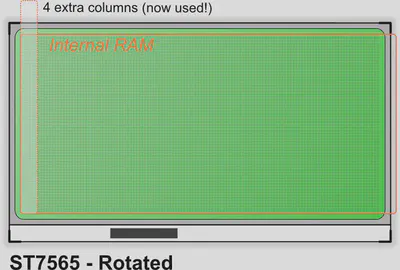
In order fix this it is necessary to keep track in software of whether the screen is rotated or not. When it is rotated the column address should be incremented by 4 each time a new line is sent to the screen, skipping the extra columns which would otherwise be displayed.
Improving efficiency
Refreshing the screen involves sending the entire local buffer to the screen RAM. If only a few changes have been made then this is a very inefficient way to update the screen.
It would be possible to send each individual write to the screen, simply by copying the single byte that has changed each time a pixel is written. However this is inefficient if more than a single bit (or pixel) is set in the same byte in subsequent operations. Changes to the screen would also be very visible at slower speeds.
As the screen has 8 pages the most efficient method on a small microcontroller is to send only the pages which have changed. Each time a pixel is set or cleared the corresponding page in the local buffer is marked as ‘dirty’. When it comes to refreshing the screen only the dirty pages are transferred.
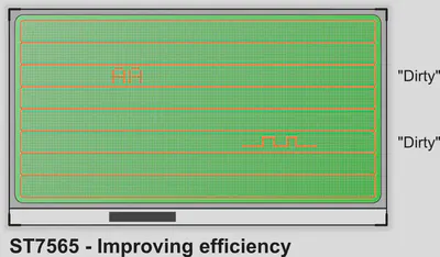
In the example above only pages 2 and 5 have had changes made. Therefore these will be sent to the screen, which takes 1/4 of the time as sending all 8 pages.
The screen could be subdivided into even smaller regions, for example 16 half pages. The trade-off of extra code each time a pixel is set and the reduced bus time sending data should be considered carefully.
Verifying speeds
Above I commented that it was possible to run a PIC at 64Mhz and not violate the SPI timings. The important values are shown in Table 28 of the datasheet:
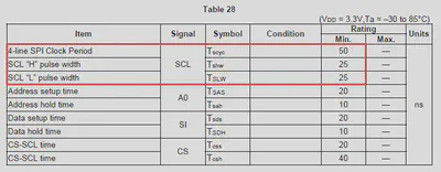
We are interested in Tscyc, Tshw and Tslw. These relate to the total clock cycle, the HIGH portion of the cycle and the LOW portion respectively. The overall clock pulse must be at least 50ns and the high and low portions must be at least 25ns each.
Crunching the numbers
Assume that the SPI code turns ON the clock pin and then OFF again immediately in 2 instructions. The pin will be HIGH at the end of the first instruction and LOW again after the second, therefore it is only HIGH for the period of 1 instruction.
On the PIC 12/16/18 family of microcontrollers each instruction takes 4 cycles. At 64Mhz this means that each instruction takes 1/(64000000/4) seconds, or 62.5ns. From this we can expect that the HIGH period of the clock pulse should be about 62.5ns, easily within the required timings.
Checking with a logic analyser
It is also possible to measure and see how long the pulse lasts on real hardware. The screenshot below shows the HIGH portion of the clock pulse being measured, this is the shortest part of the cycle. The PIC being used is an 18F25K22 running at 64Mhz. The code toggles the pin ON and OFF in two instructions.
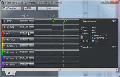
Remember that it must be at least 25ns long in order to be acceptable. The measurement shows 41.7ns, which is shorter than calculated but still acceptable. A number of reasons could produce the difference between our calculation and the physical measurement:
- The resolution of the logic analyser (24Mhz in this example) might not be sufficient for the measurement.
- Setting or clearing bits in hardware might not take the entire 4 cycles.
- The PIC might not be running at exactly 64Mhz due to instability of the oscillator or PLL.
See also
If you are interested in using a ST7565 based screen in an Arduino project then you should check out Ladyada’s tutorial on Adafruit. My C library is available which was designed for PIC 18F parts with HiTech C. It would be trivial to change for another compiler or chip.