Generating a simple sine wave
I needed a sine wave carrier for a magnetic transponder system I am working on. Various types of crystal based oscillator are available such as the Pierce, but these can be tricky to design and ensure they work correctly.
Rich suggested using a square wave oscillator with a filter to turn it into a sine wave. The filter attenuates all frequencies except the fundamental frequency, which should remove much of the square wave. Over a couple of nights I tested this in ltspice then built it on a breadboard and checked the real life results.
The circuit - theory
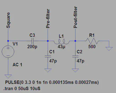
The filter used is a simple LC low pass, called a pi filter due to the shape. ltspice can easily be used to test a filter and produce an FFT to visualise the response.
The circuit used for testing is shown below and uses nothing more than a pulsed voltage source (to generate a square wave) and the filter. The value of 3.6864Mhz was chosen as it is a commonly available oscillator that divides very nicely into serial baud rates, making it excellent for serial communication.
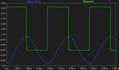
Simulating a few cycles of this provides the waveforms shown below, which verify the square wave and the resulting “sine”, which looks a little triangular at a first glance.
More important than this image is the FFT. Ideally there will be a clear 3.6864Mhz fundamental frequency with all harmonics suppressed to at most -30dB.
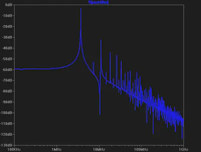
The FFT shows that the first harmonic is around -30dB, others are far below -40dB. The sine wave is not perfect in the simulation but looks quite reasonable, so it is time to build a real circuit to test.
The circuit - breadboard
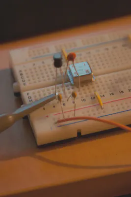
Whilst the simulator is perfect, real life is not. The circuit was built on a breadboard with an AEL crystal, Murata inductor and ordinary ceramic capacitors.
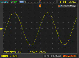
Using my Rigol DS1052E I captured data from the “post filter” node at 250Msa/sec for 1Meg worth of samples, using the “long memory” option. The graphic below shows the slightly rough sine wave, the frequency counter at the top right clearly shows an almost exact 3.6864Mhz reading.
This was fed into Sigview (a time limited demo is available that works well). A basic FFT was produced from the CSV data which clearly shows a strong peak at 3.6864Mhz and all harmonics below -60dB. These results are excellent and exceeded what I expected from my initial tests.
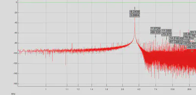
These results might improve on a real PCB, stray capacitance on the breadboard is not always good for circuits involving a crystal.
The maths
The following equation can be used to calculate the cut-off frequency of the low pass filter that was designed:
$$ \frac{1}{2\pi \times \sqrt{L \times C}} \text{Hz} $$
With the values from above of 43uH and 94pF (2*47pF) this works out as:
$$ \frac{1}{2\pi \times \sqrt{(43 \times 10^{-6}) \times (94 \times 10^{-12}) }} \text{Hz} $$
Which gives a cut-off of approximately 5Mhz using standard value components. SMD parts are often available in a wider selection of values for the same price so a more specific filter could be designed on a PCB. However this is still well below the 2nd harmonic frequency (7.3728Mhz) so is a perfectly acceptable filter.
Conclusion
Although this sine wave is nowhere near as clean as a proper crystal or DDS generated signal it is cheap, simple to construct and should work as a carrier for low frequency digital transmission to an acceptable degree. The total cost is around £3 in single quantities and would be much cheaper at volume.
David Cannings
Cyber Security
My interests include computer security, digital electronics and writing tools to help analysis of cyber attacks.